Mic pre-amp
building a pre-amp box for contact microphones
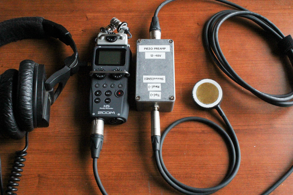
Different sources pointed out that when you work with Piezo contact mics it’s best to use a pre-amp to get the best possible audio quality. Such a device uses a high impedance input buffer. Because if you connect a Piezo element directly to your recorder or the input channel of your mixing desk, there will be an impedance mismatch and that just doesn’t sound good at all. So I taught I’d build one myself and post about it here.
enclosure
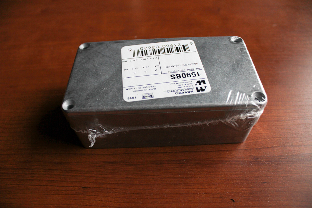
I choose this box from Hammond because it is metal and therefor very sturdy and shielding the circuit inside. Links at the bottom of this page.
fitting pre-amp circuit
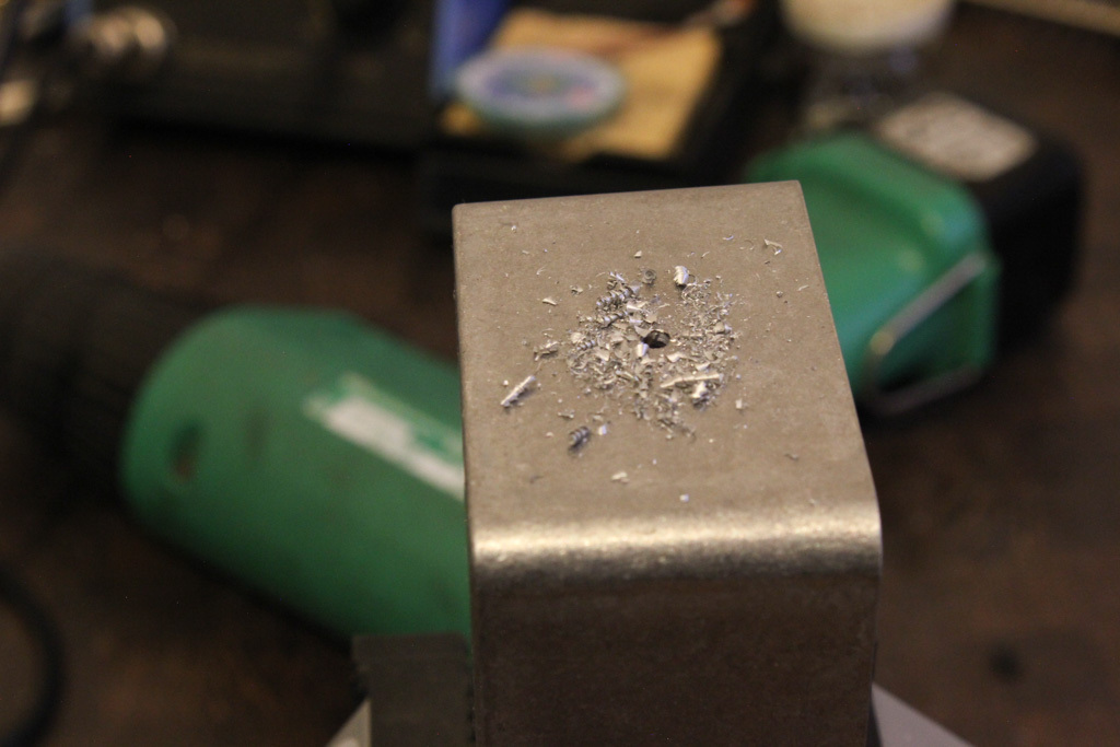
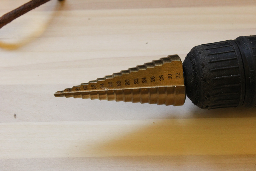
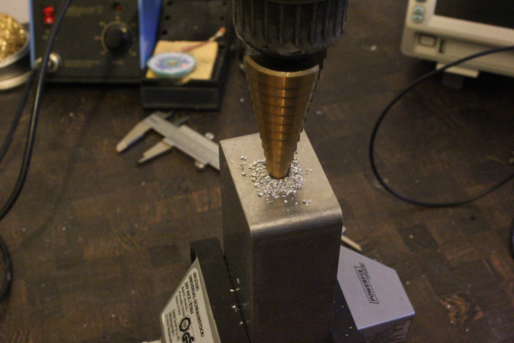
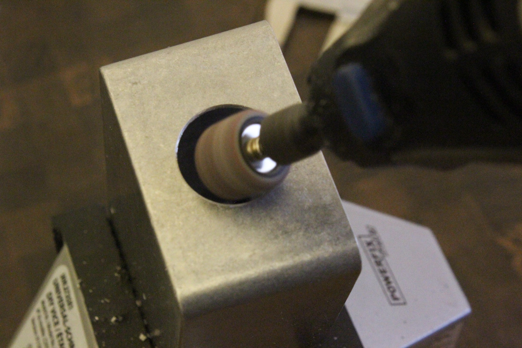
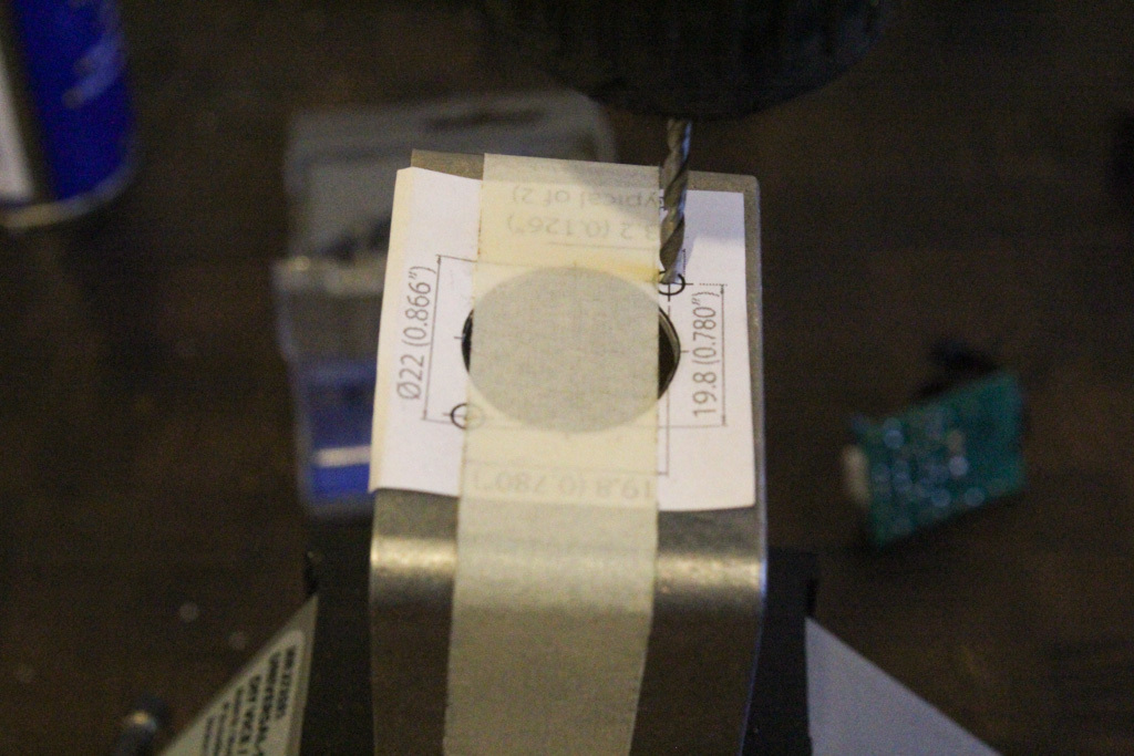
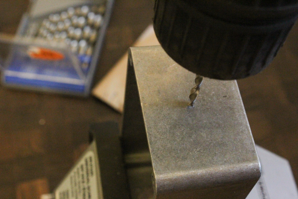
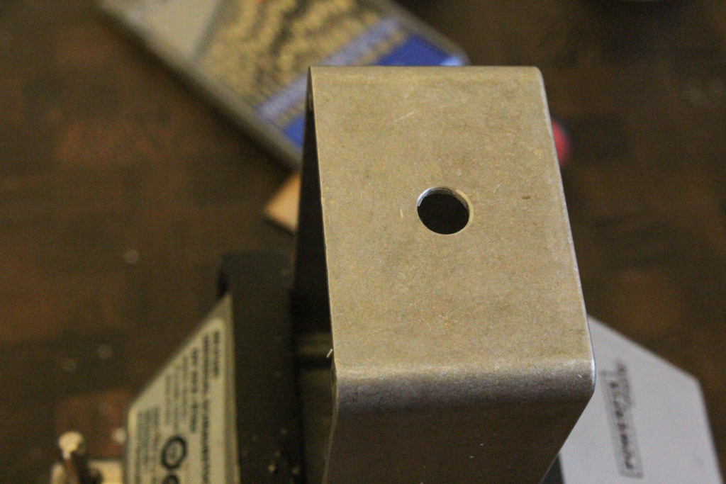
Drilling and sanding the hole to mount the XLR connector which is attached to the circuit board? All basic stuff. Just make sure that the PCB won’t touch the case. This step drill bit is pretty handy!
the circuit
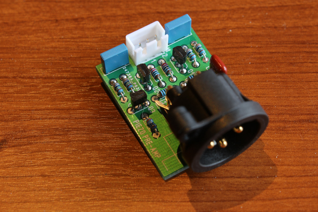
When I decided to use a pre-amp for my contact mics I started doing some research on the web and noticed the same circuit – or some variation thereof – kept popping up. A circuit for a Phantom powered Piezo pre-amp module. And when I found a small company called Stompville that sold them fully assembled I just went and ordered that one. For the price I couldn’t build it myself. You can find an improved version of this circuit here
So for everything to work correctly, using this circuit, you need to supply it with a 48V Phantom power via the XLR. In my case a Zoom H5 does that. Make sure your recording device can as well.
I’ll link the some useful information I found along the way at the bottom of this page.
finishing the box
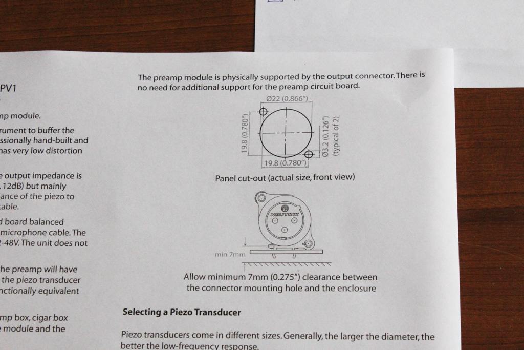
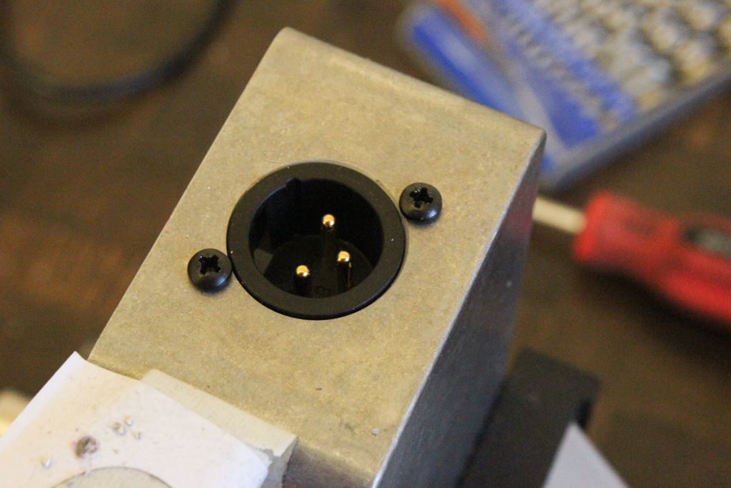
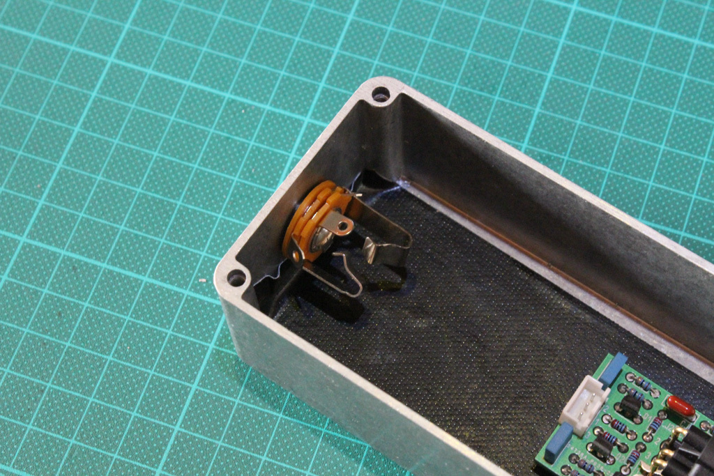
Mounting the circuit board with the XLR connector popping through. You can use the 1:1 drawing that’s printed in the user guide to get the positions for the screws right.
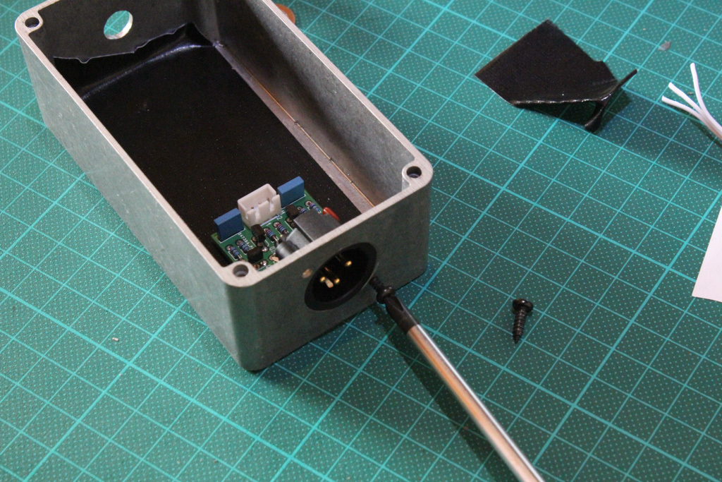
I’ve put some isolating tape on the bottom of the case to be sure there won’t be any shortage between the PCB and the case. This shouldn’t normally be a problem if you make sure there is enough clearance. But I wanted to be sure because in the field, with some rough handling the cable, the PCB might bend or some debris might get underneath it. Yes I realize I’m probably overthinking it 😉
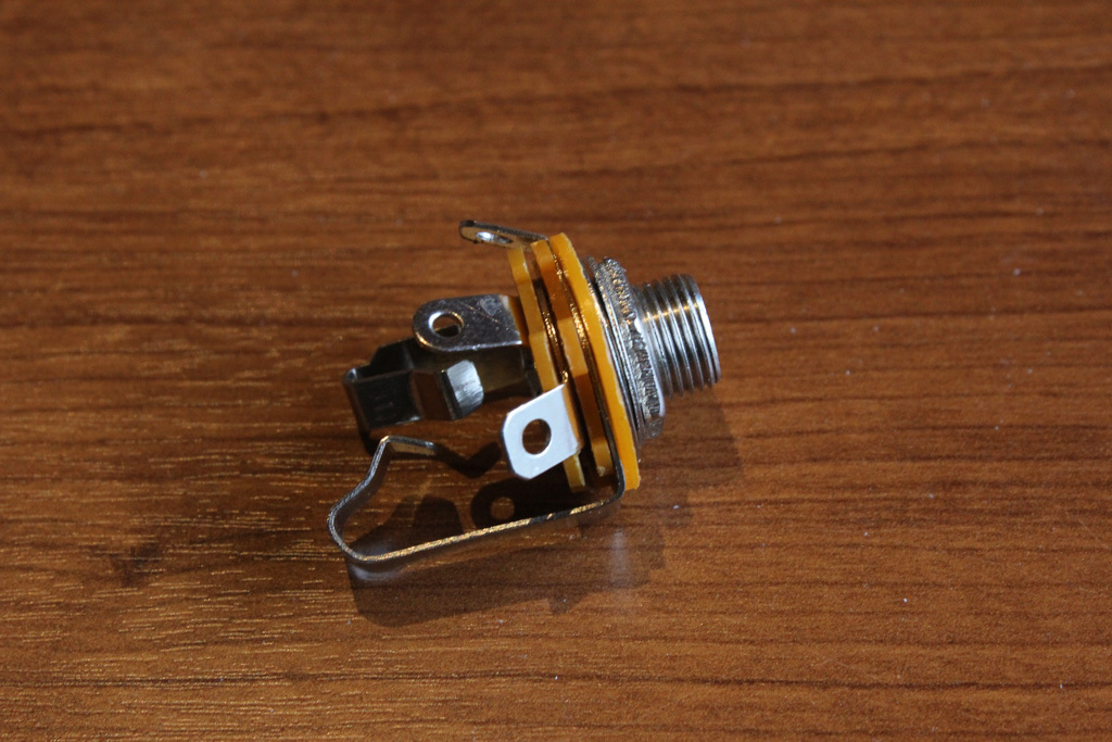
Drilling the hold for the 1/4 inch jack connector, all pretty straight forward.
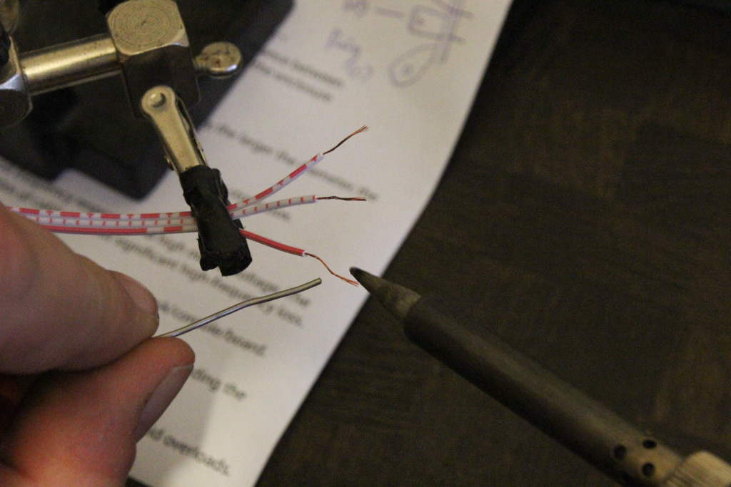
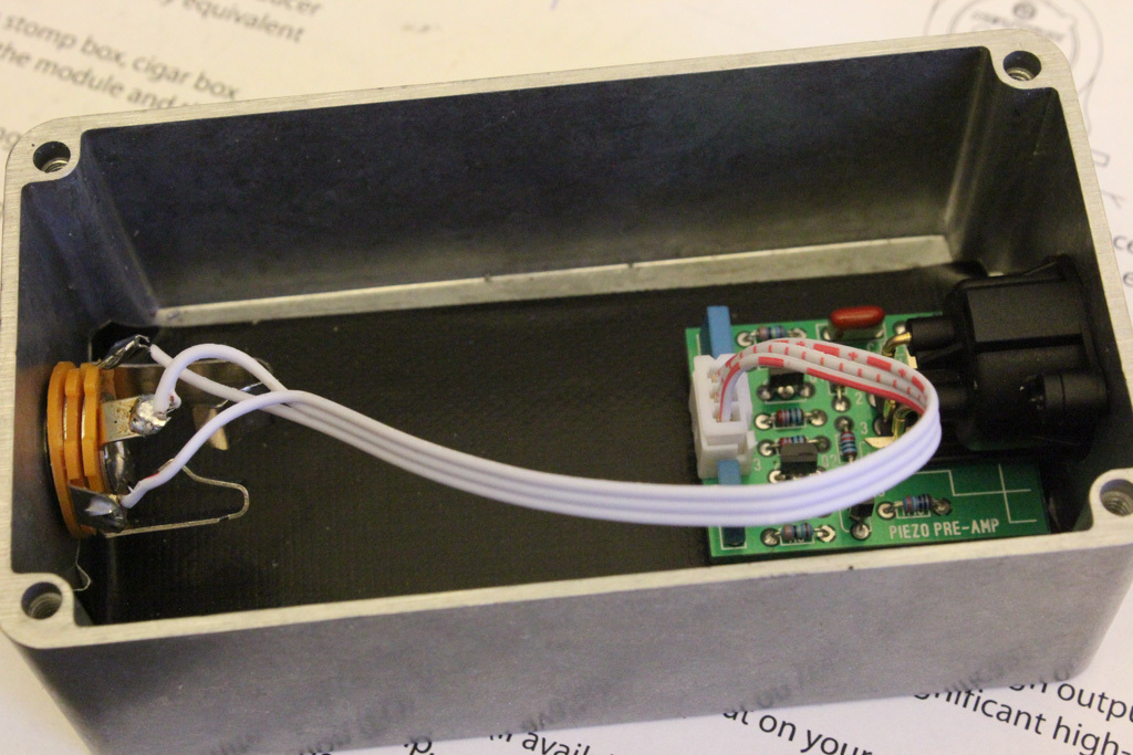
Soldering the wires from the jack connector to the board. It’s all in the user guide. 1 goes to the ground lug, 2 (+) goes to the tip lug and 3 (-) goes to the ring lug.
useful links
this project
- Phantom Piezo Preamp V2 by Stompville
- pre-amp user guide
- Hammond 1590BS natural die-cast enclosure. Dimensions
-
Stepped drill bit, always handy.
other projects / resources
-
Alex Rice Piezo Preamplifier – The original circuit
- The Cortado MKII – build instructions
- Building contact microphones